Ethernet: "the metronome"
This article is the follow-up to the first in the "Dance of Protocols" series. If you haven't read it, it's available here
Like a Sense of Déjà Vu
Do you know Ethernet? A mythical protocol of local networks, the word "Ethernet" is today used left and right in expressions that are increasingly painful (an Ethernet cable, what's that?).
It's therefore in an effort to reduce the number of people telling ignominies that I propose to study Ethernet in detail, its history and the equipment in charge of its switching.
A Bit of History
The history of the Ethernet protocol begins at Xerox Palo Alto Research Center (the same center behind the concept of graphical interface) in 1973. Robert Metcalfe, then an engineer at Xerox, was inspired by ALOHAnet, an information transmission network from the University of Hawaii, to file a patent in 1975 with David Boggs, Charles Thacker, and Butler Lampson.
Four years later, Metcalfe founded 3Com to promote the use of local networks. Convinced of the utility that Ethernet would have as a standard, he partnered with DEC, Intel, and Xerox to create the first Ethernet specification in 1980: Ethernet I (10Mb/s Ethernet) whose nickname is "DIX" (for DEC Intel Xerox). This standard would be revised in 1982 under the name Ethernet II.
In 1983, IEEE published the 802.3 standard based on DIX specifications. It should be noted that the two technologies are (fortunately) intercompatible. From this date, only IEEE would formalize updates to the standard.
But the 80s weren't exactly peaceful for Ethernet either. At the time, two other standards competed for local network territory: IBM's Token Ring and TWR-Matra's ARCnet (which no one remembers, proving La Fontaine right...). The battle was tough, but Ethernet ended up triumphing due to its topological flexibility.
"And since then?" you might ask. The reality is that Ethernet has changed very little since then (IPv6 support, throughput increases) except for one point... its physical medium!
Originally, Ethernet was a protocol that operated on a bus topology over coaxial cable, which was impractical (impedance adapter terminators, short distances, ...). Today, Ethernet is used over two different media: optical fiber and RJ45 cable. Yes, RJ45 cable and not Ethernet cable (you thought I'd forgotten my introduction question? Not at all, I was just waiting for act 2 to use my Chekhov's gun!), since the cable is only the medium that carries the protocol.
CSMA/CD, the "Metronomy" of Yesteryear
In the past, before full duplex Ethernet (technology allowing two network devices to use the medium simultaneously) became popular, the physical medium could only be used by one device at a time. If two devices happened to "speak" at the same time (and this happened very frequently in large networks), it created collisions that made communication ineffective.
To remedy this, an algorithm aimed at retransmitting frames involved in collisions was developed: Carrier Sense Multiple Access / Collision Detect (CSMA/CD). Even though it's no longer used today, it's important to understand its basic operation because it's analogous to channel sharing in Wi-Fi.
During transmission, it lasts a time \(\text{T}_t\) and takes a propagation time \(\text{T}_p\) to reach its destination.
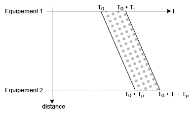
Frame transmission
If another device starts transmitting while the first hasn't finished yet, both devices will find themselves receiving and transmitting frames simultaneously, causing a collision.
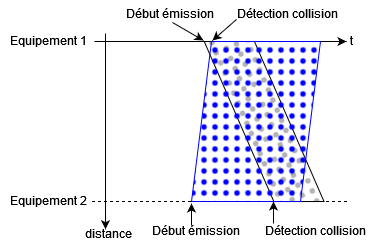
Simultaneous transmission from two devices leading to collision
A relatively simple algorithm was then implemented on any network equipment likely to encounter this problem. When a collision is detected, transmitting devices stop transmission, emit a jamming signal, then restart transmission after a random time. If collisions occur too often on the same transmission, it will be abandoned. The entire algorithm is summarized below:
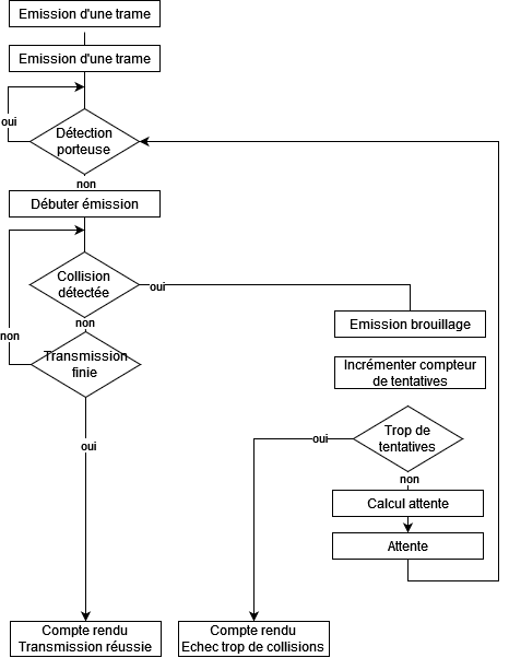
Complete CSMA/CD algorithm
To illustrate better, let's take the case where three machines are on the network:

Communication of three machines according to CSMA/CD algorithm
This algorithm works well for low throughputs (10 to 100 Mb/s) but beyond that the number of collisions would be too high and it would be absolute chaos!
Mark Kempf, the Switching Genius
A Story of Domains
Before introducing switching and bridges, let's talk a bit about the Ethernet frame to help us better understand what follows.
The Ethernet frame must be at least 64 bytes long (for collision detection) and consists of 8 fields, 5 defining the frame header and 2 the trailer.

The Ethernet frame
Let's detail the fields:
- Preamble: header part used for frame synchronization
- SFD: Start Frame Delimiter, header part indicating the actual start of the frame
- @Destination: header part, destination MAC address of the frame
- @Source: header part, source MAC address of the frame
- Type: header part indicating the type of data transmitted by the upper layer (IPv4, CDP, ...). This field violates the OSI model's layer independence principle.
- LLC data: data from the LLC sublayer (layer 2 sublayer)
- PAD (padding): trailer part, meaningless data inserted only if the LLC data field has insufficient length for collisions to be detected reliably (transmission time greater than channel time slot)
- CRC: Cyclic Redundancy Check, form of FCS (Frame Check Sequence) of degree 32 that is part of the trailer
Before bridges were developed, the way to connect computers in a network was to use a hub. A hub is a layer 1 device whose only function is to replicate the signal arriving at the input of one of its ports to all its other ports. Making no distinction on the destination address, collisions were frequent with this hardware that didn't operate in full duplex.
A hub creates a "collision domain" in which any connected device is likely to experience frame collisions.
To remedy this, an engineer from DEC, Mark Kempf, had the idea to develop a bridge (with 2 ports) whose role would be to transmit frames at the output only if they are destined for the output network. With this, the concept of frame switching based on destination MAC address was born.
An additional use of bridges was to separate two collision domains, thus creating a broadcast domain.
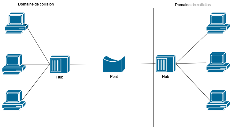
A bridge separating two collision domains created by hubs
Bridge Functions
The main function of a bridge is to transmit or not (this is called its filtering function) frames without modifying their content (LLC data, MAC addresses). It's therefore a layer 2 device.
They allow, on one hand, to increase the bandwidth of each collision domain by limiting the frames transmitted on it and, on the other hand, to increase the size of a local network almost infinitely without collision problems thanks to their filtering function.
The Learning Mechanism
Each bridge has cache memory (regularly updated) containing a database consisting of MAC addresses, corresponding connection port number, and last access date.
Initially, this memory is empty and the bridge listens in promiscuous mode (it listens to everything) to transmitted frames.
For a given frame, the bridge records its source MAC address, reception port (if not already recorded), and updates the field corresponding to its arrival time. It then searches its database for the destination MAC address.
- If it exists, it sends the frame on the associated port, or destroys it if the associated port is the same as the transmission port (local traffic). This performs its filtering function.
- If it doesn't exist, it sends the frame on all ports except the reception port.
Bridge learning
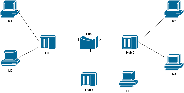
We can outline, as an example, the learning and switching steps of the bridge:
| Frame transmission from ... to ... | Reception port | Transmission ports | Bridge cache memory content | |||
|---|---|---|---|---|---|---|
| M1 \(\to\) M2 | P1 | P2 and P3 | M1 - Port 1 | |||
| M2 \(\to\) M3 | P1 | P2 and P3 | M2 - Port 1 | |||
| M3 \(\to\) M1 | P2 | P1 | M3 - Port 2 | |||
| M3 \(\to\) M4 | P2 | P1 and P3 | Update M3 date | |||
| M4 \(\to\) M3 | P2 | Destroy | M4 - Port 2 | |||
| M1 \(\to\) M2 | P1 | Destroy | Update M1 date | |||
| M1 \(\to\) M5 | P1 | P2 and P3 | Update M1 date | |||
| M5 \(\to\) M1 | P3 | P1 | M5 - Port 3 |
Bridge learning table
Full Duplex
Thanks to Kempf's bridges, then modern switches, a revolution became possible: simultaneous bidirectional communication, or "full duplex."
The principle of full duplex is simple and analogous to a highway. Rather than having a single highway lane whose direction would alternate to let cars pass, why not build a two-way highway to accommodate cars in both directions? It's the same thing for full duplex: having two devices talking simultaneously on the physical medium.
Obviously, this implies some small adjustments to network topology. Gone is Ethernet over coaxial cable where everyone shares the medium. Now, links will be point-to-point between the device and the bridge (or switch).
This transformation had major consequences: disappearance of CSMA/CD (now useless) and doubling of effective throughput (because of bidirectional communication), and elimination of all complexity related to collision management. A 24-port switch can now handle 24 simultaneous communications, each in full duplex.
With this revolution, Ethernet had found its modern form. But one challenge remained: how to efficiently make all these local networks communicate with each other? That's where our next protagonist comes in...
Conclusion
Our journey into the Ethernet universe comes to an end, and what a journey!
From the chaotic metronome of CSMA/CD to modern switches orchestrating dozens of simultaneous communications, Ethernet has evolved while keeping its essence as a local network protocol. This adaptability explains why, 50 years after its creation at Xerox PARC, this protocol still dominates our local networks and is beginning to seek its place beyond.
Mark Kempf's revolution with the bridge was the decisive turning point for the protocol's sustainability: transforming a shared and conflicting medium into an efficient point-to-point infrastructure. Full duplex was then just a logical consequence of this vision.
Ethernet has found its rhythm, its perfect metronome. But how do local networks communicate with each other? How does a packet travel from one network to another?
That's where our first dancer comes in...
Next episode: IP, "the universal carrier" - Why this layer 3 protocol became the de facto standard for communications.